
EDIT (12-Dec-22)
- Added a “Let’s Hear It!” section to give folks an idea of the sound.
- Added “Another Disclaimer” section for those who want to dive deep into more of the nuances of hard clipping with a DSP (and why it’s hard to make it sound pleasant).
- Adjusted code slightly to make distortion more apparent.
Teensy DSP Series – Part II
This is the second installment of a series of posts that will revolve around Teensy as a DSP. In this post, we’ll implement the classic effect of distortion!
Introduction
Now that we can see what our signal looks like as it passes through the DSP let’s see what things will look like when we distort our signal. Distortion is one of the most common effects for effect pedals. And there’s a reason for that! In this post, we’ll go into more detail about how we can use our DSP to distort our signal and get that quintessential rock sound we’re all familiar with.
What Is Distortion?
So, you can probably skip this section if you’re experienced with pedals and building. But for folks that might be familiar with distortion, let’s talk about what exactly it is. Distortion is what you get when your audio signal runs out of room for its output device. Sound from your instrument travels in waves, with peaks up and down. When you output your signal through something like an amp, the amp has a certain amount of audio output before the waveform exceeds what it’s capable of outputting. This is why so many guitarists back in the day would crank their amps and get the textbook sound that so many of us have heard through the recordings that we love. They’re pushing a waveform that’s “bigger” than what their output device can handle.
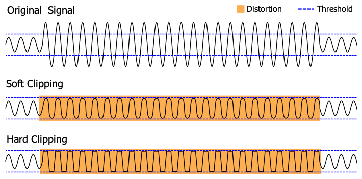
When these output devices reach their output limit, they start to “distort” their signal via clipping (as seen in the image to the right). They can’t output anything further than they can because they’ve exhausted their headroom (for various reasons), so the sound you get is clipped and distorted. And for some strange (but awesome!) reason, it produces a sound that many of us love.
Now, I do have to give a bit of a disclaimer here: there are more types of distortion than I described above. Things such as bit crushing, saturation, and other effects create distorted sounds. But what I mentioned above is called “clipping” distortion, where a signal is “clipped” past a certain point. For this post, we’ll be covering this kind of distortion because it’s the easiest for us to talk about and map back to many of the common forms of distortion that we see from distortion guitar effect pedals.
Getting Our Signal Clipped
Let’s pick up where we last left off in our previous post. To review, we were able to get a signal passing through our Teensy and visualize the signals. With that under our belt, let’s figure out how we will add distortion to our signal. To start, we’ll use a tool called the “Audio System Design Tool” that’s offered as part of Teensy’s Audio library that gives us a visual representation of our audio pipeline. As we add more effects or make more changes to our code, we’ll want to regularly consult this page because it’s the best way to ensure that we know how things flow.
Understanding Our Audio Chain
Now, with the Audio System Design Tool open, click the “Import” button and paste the following section of code from our previous post into the window:
// ...

AudioInputI2S            i2s1;
AudioMixer4              mixer4;
AudioRecordQueue         queue1;
AudioRecordQueue         queue2;
AudioOutputI2S           i2s2;
AudioConnection          patchCord1(i2s1, 0, queue1, 0);
AudioConnection          patchCord2(i2s1, 0, mixer4, 0);
AudioConnection          patchCord4(i2s1, 1, mixer4, 1);
AudioConnection          patchCord5(mixer4, queue2);
AudioConnection          patchCord6(mixer4, 0, i2s2, 0);
AudioConnection          patchCord7(mixer4, 0, i2s2, 1);

// ....
Once done, click “Ok.” You’ll notice that everything is bunched up and hard to make sense of (sorry about that!). We’ll need to do some dragging to make things look reasonable. Click each box and drag it until it is similar to the “End State” image below. The positioning doesn’t have to be exact since what matters here are the connections between the nodes, so don’t fret over pixels and positions; make sure it’s something that you can make sense of.
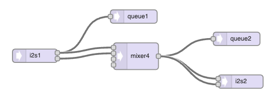
Congrats! You’re now seeing what the audio chain that you’ve been working with is made of. I’ll explain at a high level, but if you’re curious about any component, feel free to click the node in question–the pane on the right of the window will provide more details. Starting on the right, we have our input (i2s1). This forks to queue1, which stores the signal from our input. Queue1 is what we see as a blue waveform when we open the serial plotter.
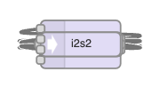
i2s1 also forks to mixer4 (don’t read into why there’s a ‘4’ at the end; I’m honestly not sure; probably how I copied it 🤷♂️). We don’t do much with this mixer aside from merging our input’s left and right output channels into a single source. From there, mixer4 goes out to queue2 (the other waveform we have in our plotter) and then to the right and left channels of our output–i2s2.
All in all, this is pretty simple: Input -> Mixer -> Output. Now, let’s get to the good part: making distortion work!
Updating Our Audio Chain
Using the Audio System Design Tool, we’re going to add one of the following components: waveshape and amp. Arrange them with the connections that you see in the next image. You may have to delete some connecting lines and redraw them so they connect appropriately. If you’re having trouble with it, you can check out the code further in this post and Import it to recreate the correct layout.
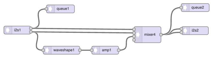
Let’s talk about what we’ve added here. First off, waveshape1. We’ll use this to change the waveform that is output from our guitar. After that, we have an amp. We put this after the waveshape to attenuate the signal. Since our waveform will be clipping, we’ll have a decent amount of gain. We’ll want to turn the gain down after altering the waveform, so the distortion isn’t jarring.
So we have our pipeline; great! Now, let’s update our code so we can use the pipeline to distort our signal.
Adding Distortion Code
Let’s open our Teensyduino editor and update our code to use these new parts. Copy and replace the code in your editor with the following; then, we’ll go over the new sections:
/*
 * Copyright 2022 Straight to Ground LLC
 * Permission is hereby granted, free of charge, to any person obtaining a copy of this software and associated documentation files (the "Software"), to deal in the Software without restriction, including without limitation the rights to use, copy, modify, merge, publish, distribute, sublicense, and/or sell copies of the Software, and to permit persons to whom the Software is furnished to do so, subject to the following conditions:
 *
 * The above copyright notice and this permission notice shall be included in all copies or substantial portions of the Software.
 *
 * THE SOFTWARE IS PROVIDED "AS IS", WITHOUT WARRANTY OF ANY KIND, EXPRESS OR IMPLIED, INCLUDING BUT NOT LIMITED TO THE WARRANTIES OF MERCHANTABILITY, FITNESS FOR A PARTICULAR PURPOSE AND NONINFRINGEMENT. IN NO EVENT SHALL THE AUTHORS OR COPYRIGHT HOLDERS BE LIABLE FOR ANY CLAIM, DAMAGES OR OTHER LIABILITY, WHETHER IN AN ACTION OF CONTRACT, TORT OR OTHERWISE, ARISING FROM, OUT OF OR IN CONNECTION WITH THE SOFTWARE OR THE USE OR OTHER DEALINGS IN THE SOFTWARE.
**/

// Shout out to h4yn0nnym0u5e at the pjrc forum for the inspiration/code bits
// https://forum.pjrc.com/threads/69900-Non-realtime-audio-debugging

#include <Audio.h>
// Not needed if you're not using the BlackAddr audio shield
#include "BALibrary.h"

// GUItool: begin automatically generated code
AudioInputI2S            i2s1;           //xy=139.88888549804688,409.9999988898635
AudioRecordQueue         queue1;         //xy=299.8888854980469,330.9999988898635
AudioEffectWaveshaper    waveshape1;     //xy=303.8888854980469,484.9999988898635
AudioAmplifier           amp1;           //xy=465.8888854980469,484.9999988898635
AudioMixer4              mixer4;         //xy=622.8888854980469,426.9999988898635
AudioOutputI2S           i2s2;           //xy=798.8888854980469,411.9999988898635
AudioRecordQueue         queue2;         //xy=799.8889122009277,326.0000247955322
AudioConnection          patchCord1(i2s1, 0, queue1, 0);
AudioConnection          patchCord2(i2s1, 0, mixer4, 0);
AudioConnection          patchCord3(i2s1, 1, waveshape1, 0);
AudioConnection          patchCord4(i2s1, 1, mixer4, 1);
AudioConnection          patchCord5(waveshape1, amp1);
AudioConnection          patchCord6(amp1, 0, mixer4, 2);
AudioConnection          patchCord7(mixer4, 0, i2s2, 0);
AudioConnection          patchCord8(mixer4, 0, i2s2, 1);
AudioConnection          patchCord9(mixer4, queue2);
// GUItool: end automatically generated code

// Change this to whatever codec your shield uses
BALibrary::BAAudioControlWM8731 codecControl;

static int graphingDelay = 0;

#define COUNT_OF(x) ((int32_t)(sizeof x / sizeof x[0]))

// ADDED: Put new queue (queue3) into the collection
AudioRecordQueue* queues[] = {&queue1,&queue2};
int16_t* dptrs[COUNT_OF(queues)];

bool outputEnabled = true;
void processQueues(void)
{
  for (int i=0;i<COUNT_OF(queues);i++)
    dptrs[i] = queues[i]->readBuffer();

  // actual processing:
  if (outputEnabled)
  {
    for (int j=0;j<AUDIO_BLOCK_SAMPLES;j++)
    {
      for (int i=0;i<COUNT_OF(queues);i++)
        Serial.printf("%d ",dptrs[i][j]);
      Serial.println();
      delay(graphingDelay);
    }
  }

  for (int i=0;i<COUNT_OF(queues);i++)
    queues[i]->freeBuffer();
}

/*
 * ADDED: Set the length of the waveshape and initialize
 * the waveshape array.
 */
const int WAVESHAPE_LENGTH = 8193;
float WAVESHAPE[WAVESHAPE_LENGTH] = {};

void setup()
{
  AudioNoInterrupts(); // freeze the audio system

  // wait for serial connection to be established
  Serial.begin(115200);

  AudioMemory(64);
  codecControl.disable();
  delay(100);
  codecControl.enable();
  delay(100);

  // ADDED: Set the values in the waveshape to a square waveform.
  for (int i = 0; i < (WAVESHAPE_LENGTH-1)/2; i++) {
    WAVESHAPE[i] = -1.0;
    WAVESHAPE[WAVESHAPE_LENGTH - 1 - i] = 1.0;
  }
  WAVESHAPE[(WAVESHAPE_LENGTH-1)/2] = 0.0;


  // ADDED: Values to the waveshape object in our audio pipeline
  waveshape1.shape(WAVESHAPE, WAVESHAPE_LENGTH);
  // ADDED: Set the gain of amp1 to attenuate the signal from the waveshape
  amp1.gain(0.9);
  // ADDED: Set the gain to line strength in the mixer to ensure we can hear
  mixer4.gain(0, 0.9);
  mixer4.gain(1, 0.9);
  mixer4.gain(2, 1.0);
  mixer4.gain(3, 1.0);

  for (int i=0;i<COUNT_OF(queues);i++)
    queues[i]->begin();

  // output graph legend (updated)
  Serial.println("clean mixed");
}


int next;
void loop()
{
  if (queue1.available()) // assume if there's data for queue1, there's data for all
  {
    AudioNoInterrupts();
    processQueues();
    next = 250;
  }
  else
    AudioInterrupts();

  if (Serial.available())
  {
    while (Serial.available())
      Serial.read();

    outputEnabled = !outputEnabled;
  }

  // output dots if something's not working
  delay(1);
  if (--next < 0)
  {
    next = 250;
  }
}
Code Additions
Here’s the breakdown of the changes. If you get the idea, you can move to the next section.
/*
 * ADDED: Set the length of the waveshape and initialize
 * the waveshape array.
 */
const int WAVESHAPE_LENGTH = 8193;
float WAVESHAPE[WAVESHAPE_LENGTH] = {};
Here we set the length of the waveshape we created, then initialize an array of floats that will describe the waveshape by numbers.
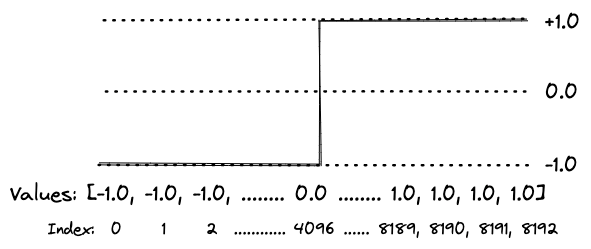
  // ADDED: Set the values in the waveshape to a square waveform.
  for (int i = 0; i < (WAVESHAPE_LENGTH-1)/2; i++) {
    WAVESHAPE[i] = -1.0;
    WAVESHAPE[WAVESHAPE_LENGTH - 1 - i] = 1.0;
  }
  WAVESHAPE[(WAVESHAPE_LENGTH-1)/2] = 0.0;
Here we set the shape of the waveshape. This loop will assign values on the “left” of the array to -1.0. The “right” side of the array will be 1.0. The “middle” is 0.0 to bridge the gap between the peak and trough. Our waveshape, as defined, ends up looking something like this:
Then we set up the amp after this waveshape to attenuate–or lower–the audio level.
  // ADDED: Values to the waveshape object in our audio pipeline
  waveshape1.shape(WAVESHAPE, WAVESHAPE_LENGTH);
  // ADDED: Set the gain of amp1 to attenuate the signal from the waveshape
  amp1.gain(0.9);
  // ADDED: Set the gain to line strength in the mixer to ensure we can hear
  mixer4.gain(0, 0.9);
  mixer4.gain(1, 0.9);
  mixer4.gain(2, 1.0);
  mixer4.gain(3, 1.0);
Setting the amp’s gain to lower than 1.0 prevents the distortion from being overbearing or jarring. We then set the gain to our mixer to be line level so we can pass the distorted signal to our output.
Now that we’ve gone over the changes let’s compile and upload our code to our Teensy so we can see the effect on our signal!
A Quick Disclaimer
So I have to come clean before we run this code: we’re reaching the limits of what we can do with our plotting code. Because of how this code is written, the audio signal needs to be halted for the queues to drain to graph what we see on the plotter. Disabling and enabling audio results in an audible “click.” If you don’t end up hearing this when running this code, you are lucky and not many code updates away from hearing it. When it happens, it’ll probably ruin things for you.
Additionally, for some reason (unknown to me), you may also see some artifacts in the plotter. It’ll manifest as new signals showing up (new colors). I have some ideas on why this is happening, but I’ll avoid the rabbit hole. For now, ignore these. You’ll want to focus on the blue and red lines, the colors of our waveforms. Again, we’re pushing limits here and will probably have to drop plotting support in our code soon.
Later in this post, I’ll provide some updated code allowing toggling the plotting logic. If you want to hear the distortion without clicking, scroll down to find it!
Testing Our Distortion
Now that I’ve given you a disclaimer and you’re not going to think your Teensy is broken go ahead and click “Upload” in Teensyduino to get this code running. Also, ensure that you have your Serial Plotter open. If you open it after the Teensy starts, you may have a working legend at the top. If this happens, unplug the Teensy and plug it in again. Your computer will pick up the serial USB connection once the Teensy is back up, and you should see data start streaming again.
With all this ready, give your guitar a hefty strum and enjoy the distorted goodness! Pay attention to the signals that are drawn in the plotter. Notice something interesting?

For those that may not be seeing it, how about we look back at the signal that we observed in the previous post with a clean signal:
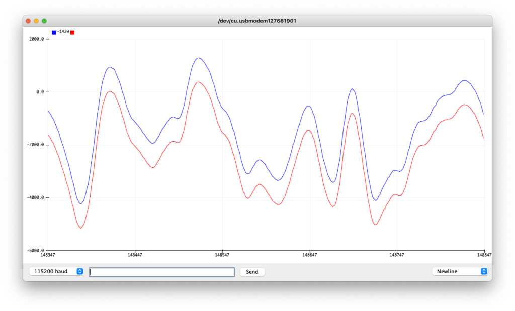
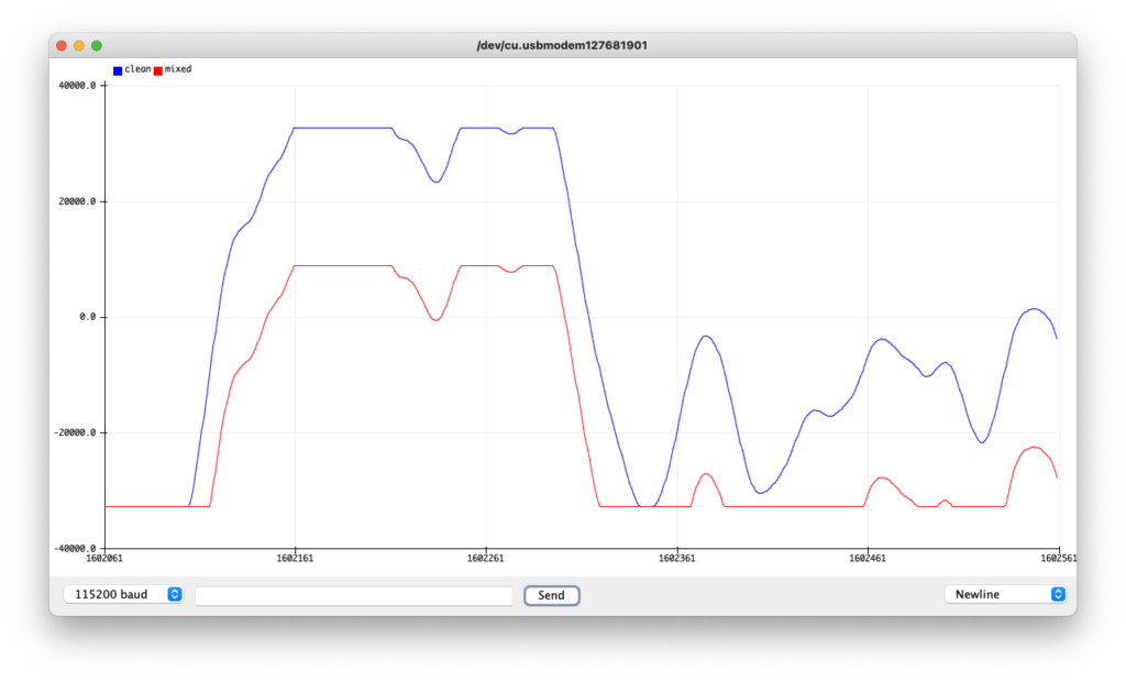
You probably see it now–your distorted signal is clipped at the peak and trough! And with your ears, I’m sure you’ve noticed that you’re no longer hearing the clean tone you had before. Now, you’re able to hear your guitar with a distorted tone. And there you have it, your DSP-driven distortion!
Let’s Hear It!
Would you believe I initially put this thing up without any audio?! Thanks to gtt in the comments for suggesting that I include audio samples. Below you can hear both a clean strum of a G power chord, followed the same, but with our distortion applied:
Another Disclaimer
Now, if you’ve taken a stab at playing around with any of the parameters around gain in the code above, you’ve probably realized that things sound kind of terrible when the gain on the distortion is turned up. And well… There’s a (complicated to me) reason for that! Suffice it to say, I’m not the best person to provide a detailed explanation for it, but the folks on Hacker News had a great discussion around this topic and could probably point you to some great topics if you’re looking to get deep into the theory behind what we’ve done above.
Wrapping Up
So there you have it, distortion! With our Teensy DSP’s help, we can achieve a similar effect to what we see with diodes in circuits for analog guitar pedals. Even better, you can visualize how it affects your signal to create that distinct sound we love. Additionally, you’ve learned a bit more about the Teensy Audio pipeline and how to leverage it to add your effects to your signal.
And this is just the beginning! Stay tuned and follow us on social media to be the first to know when we the next part of our Teensy DSP Series:
Appendix A – Code With Plotting Toggle
As promised, here’s the code that allows you to toggle. Use this if you’re hearing clicking or odd audio artifacts:
/*
 * Copyright 2022 Straight to Ground LLC
 * Permission is hereby granted, free of charge, to any person obtaining a copy of this software and associated documentation files (the "Software"), to deal in the Software without restriction, including without limitation the rights to use, copy, modify, merge, publish, distribute, sublicense, and/or sell copies of the Software, and to permit persons to whom the Software is furnished to do so, subject to the following conditions:
 *
 * The above copyright notice and this permission notice shall be included in all copies or substantial portions of the Software.
 *
 * THE SOFTWARE IS PROVIDED "AS IS", WITHOUT WARRANTY OF ANY KIND, EXPRESS OR IMPLIED, INCLUDING BUT NOT LIMITED TO THE WARRANTIES OF MERCHANTABILITY, FITNESS FOR A PARTICULAR PURPOSE AND NONINFRINGEMENT. IN NO EVENT SHALL THE AUTHORS OR COPYRIGHT HOLDERS BE LIABLE FOR ANY CLAIM, DAMAGES OR OTHER LIABILITY, WHETHER IN AN ACTION OF CONTRACT, TORT OR OTHERWISE, ARISING FROM, OUT OF OR IN CONNECTION WITH THE SOFTWARE OR THE USE OR OTHER DEALINGS IN THE SOFTWARE.
**/

// Shout out to h4yn0nnym0u5e at the pjrc forum for the inspiration/code bits
// https://forum.pjrc.com/threads/69900-Non-realtime-audio-debugging

// Comment this line out if you wish to disable Serial Plotting
//#define ENABLE_PLOTTING

#include <Audio.h>
// Not needed if you're not using the BlackAddr audio shield
#include "BALibrary.h"

// GUItool: begin automatically generated code
AudioInputI2S            i2s1;           //xy=139.88888549804688,409.9999988898635
AudioRecordQueue         queue1;         //xy=299.8888854980469,330.9999988898635
AudioEffectWaveshaper    waveshape1;     //xy=303.8888854980469,484.9999988898635
AudioAmplifier           amp1;           //xy=465.8888854980469,484.9999988898635
AudioMixer4              mixer4;         //xy=622.8888854980469,426.9999988898635
AudioOutputI2S           i2s2;           //xy=798.8888854980469,411.9999988898635
AudioRecordQueue         queue2;         //xy=799.8889122009277,326.0000247955322
AudioConnection          patchCord1(i2s1, 0, queue1, 0);
AudioConnection          patchCord2(i2s1, 0, mixer4, 0);
AudioConnection          patchCord3(i2s1, 1, waveshape1, 0);
AudioConnection          patchCord4(i2s1, 1, mixer4, 1);
AudioConnection          patchCord5(waveshape1, amp1);
AudioConnection          patchCord6(amp1, 0, mixer4, 2);
AudioConnection          patchCord7(mixer4, 0, i2s2, 0);
AudioConnection          patchCord8(mixer4, 0, i2s2, 1);
AudioConnection          patchCord9(mixer4, queue2);
// GUItool: end automatically generated code

// Change this to whatever codec your shield uses
BALibrary::BAAudioControlWM8731 codecControl;

static int graphingDelay = 0;

#define COUNT_OF(x) ((int32_t)(sizeof x / sizeof x[0]))

// ADDED: Put new queue (queue3) into the collection
AudioRecordQueue* queues[] = {&queue1,&queue2};
int16_t* dptrs[COUNT_OF(queues)];

bool outputEnabled = true;
void processQueues(void)
{
  for (int i=0;i<COUNT_OF(queues);i++)
    dptrs[i] = queues[i]->readBuffer();

  // actual processing:
  if (outputEnabled)
  {
    for (int j=0;j<AUDIO_BLOCK_SAMPLES;j++)
    {
      for (int i=0;i<COUNT_OF(queues);i++)
        Serial.printf("%d ",dptrs[i][j]);
      Serial.println();
      delay(graphingDelay);
    }
  }

  for (int i=0;i<COUNT_OF(queues);i++)
    queues[i]->freeBuffer();
}

/*
 * ADDED: Set the length of the waveshape and initialize
 * the waveshape array.
 */
const int WAVESHAPE_LENGTH = 8193;
float WAVESHAPE[WAVESHAPE_LENGTH] = {};

void setup()
{
#ifdef ENABLE_PLOTTING
  AudioNoInterrupts(); // freeze the audio system
#endif
  // wait for serial connection to be established
  Serial.begin(115200);

  AudioMemory(64);
  codecControl.disable();
  delay(100);
  codecControl.enable();
  delay(100);

  // ADDED: Set the values in the waveshape to a square waveform.
  for (int i = 0; i < (WAVESHAPE_LENGTH-1)/2; i++) {
    WAVESHAPE[i] = -1.0;
    WAVESHAPE[WAVESHAPE_LENGTH - 1 - i] = 1.0;
  }
  WAVESHAPE[(WAVESHAPE_LENGTH-1)/2] = 0.0;


  // ADDED: Values to the waveshape object in our audio pipeline
  waveshape1.shape(WAVESHAPE, WAVESHAPE_LENGTH);
  // ADDED: Set the gain of amp1 to attenuate the signal from the waveshape
  amp1.gain(0.9);
  // ADDED: Set the gain to line strength in the mixer to ensure we can hear
  mixer4.gain(0, 0.9);
  mixer4.gain(1, 0.9);
  mixer4.gain(2, 1.0);
  mixer4.gain(3, 1.0);

#ifdef ENABLE_PLOTTING
  for (int i=0;i<COUNT_OF(queues);i++)
    queues[i]->begin();

  // output graph legend (updated)
  Serial.println("clean mixed");
#endif
}


int next;
void loop()
{
#ifdef ENABLE_PLOTTING
  if (queue1.available()) // assume if there's data for queue1, there's data for all
  {
    AudioNoInterrupts();
    processQueues();
    next = 250;
  }
  else
    AudioInterrupts();

  if (Serial.available())
  {
    while (Serial.available())
      Serial.read();

    outputEnabled = !outputEnabled;
  }

  // output dots if something's not working
  delay(1);
  if (--next < 0)
  {
    next = 250;
  }
#endif
}
Pingback: Diodes hate it! Clipping and distortion with DSPs #Audio @straight2ground « Adafruit Industries – Makers, hackers, artists, designers and engineers!
Pingback: Diodes hate it! Clipping and distortion with DSPs #Audio @straight2ground – Radio News Music Blog
Suggestion: Can you put audio samples on here?
Great suggestion! Let me get some recording software installed and I’ll figure out how to get them up.
Added!